Some time ago I was asked, if I could build a controller for a photo booth. Here it is.
Since December 2017 the project is public domain. Schematics and software are available for download (see below). The manual is available in German language only. The interface itself is in English, so it should be quite intuitive. A help command ? is available.
Why a Controller?
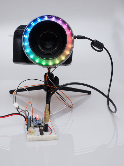
Photo booths have to be intuitive. Users want to know, if the booth is ready for action or if it needs a break for processing. Users also want to know, if pressing the button was accepted.
My controller leads users through the process of taking the picture. An LED ring placed around the lens (or lens opening in the box) is used as a status display. In addition, a buzzer light can be driven by the controller. The shown LED ring consists of 20 LEDs and has an inner diameter of 77mm. Other numbers of LEDs or diameters are available on request.
User Interface
The controller defines the following sequence of actions.
- When idle, the LED ring shows a rotating rainbow. The buzzer contact is active and the buzzer is illuminated. The camera release is half “pressed” in intervalls to prevent the camera from falling into a deep sleep mode.
- Pushing the buzzer starts a count-down sequence. LEDs are switched off (selectable clockwise or counterclockwise) to show the time remaining until shutter release.
- While the autofocus is allowed to work, all LEDs are lit in white. At the end of this phase, the shutter is released.
- During a post-processing phase a rotating red segment signals that the system is busy. This phase may be used to process or transfer the image data. The light in the buzzer is slowly dimmed on to announce readyness.
- Then, the system resumes with the idle state.
All parts of the sequence are configurable in speed and duration. The number of controlled LEDs in the ring can also be set by the user. You only need a terminal software to set parameters via USB. This may be done with a PC, a tablet or even with a mobile phone. The most important parameters may be configured through the buzzer button without any tools.

The PCB features the following connections:
- Power supply with 5V, 1200mA.
- 3,5mm stereo jack for camera control. To protect the camera, the circuit is decoupled by an optocoupler.
- Pinhead for an illuminated buzzer.
- Pinhead for the LED-ring.
- 3,5mm mono jack to connect a wireless transmitter or another button release.
- Toggle switch to select normal operation or service mode.
- USB-connector for configuration and software update. May also be used to power the controller.
Circuitry and Schematics
The controller was designed with variants. Not all components have to be soldered if you want to keep it cheap. The power supply (1) may be left out. The USB connector (7) will power the system with a 20 (or less) LED ring. The release connectors (3) and (5) share the same functionality regarding release functionality. Connector (3) features an additional LED driver for an illuminated buzzer.
Software
The latest version of the software is available for download below. It is based on an Arduino Nano platform and uses the open-source libraries EEPROM and Adafruit_NeoPixel.
Further information
Requests may be placed through the contact form.